rotate and perspective
Technical information
- description
- rotate or distort perspective.
- purpose
- corrective or creative.
- input
- linear, RGB, scene-referred.
- processing
- geometric, RGB.
- output
- linear, RGB, scene-referred.
Automatically correct for converging lines, a form of perspective distortion. The underlying mechanism is inspired by Markus Hebel’s ShiftN program. This module also allows for the rotation of the image to be adjusted.
Perspective distortions are a natural effect when projecting a three dimensional scene onto a two dimensional plane and cause objects close to the viewer to appear larger than objects further away. Converging lines are a special case of perspective distortions frequently seen in architectural photographs – parallel lines, when photographed at an angle, are transformed into converging lines that meet at some vantage point within or outside of the image frame.
This module is able to correct converging lines by warping the image in such a way that the lines in question become parallel to the image frame. Corrections can be applied in a vertical and horizontal direction, either separately or in combination. In order to perform automatic correction the module is able to analyze the image for suitable structural features consisting of line segments. You can also set the line structures manually by drawing a “perspective rectangle” or drawing multiple horizontal and vertical lines onto the image. Based on these (automatic or manually-drawn) line segments a fitting procedure is initiated, which determines the best values for the module’s parameters.
As the most common use case for this module is for rotation, the perspective correction controls are hidden by default. Click the “perspective” header to expand the controls.
While the module is active (and none of the structure buttons are selected) you can right-click and drag anywhere on the image to define a horizontal or vertical line. This will cause the rotation parameter to be automatically adjusted to make the drawn line horizontal/vertical with respect to the image frame.
Note: This functionality (right-click and drag to set horizontal/vertical) is also available when the module is inactive, as long as no other function (e.g. drawn mask creation) claims the right-hand mouse button.
🔗perspective correction workflow
🔗structure
The first step is to obtain details about the horizontal and/or vertical structures in the image. Three alternative methods are provided to do this:
🔗manually draw structure lines
Click on the
![]() icon to enable line drawing mode and then click-and-drag on the image to draw lines that you wish to become horizontal or vertical. The module will automatically detect whether the lines are horizontal or vertical and color them green or blue, respectively. Draw as many lines as you wish (the more lines, the better the fit mechanism will work) and then click on one of the “fit” icons to complete the process. You can re-enter this mode to edit your drawn lines at any time. Edit a line by clicking and dragging on the line or the end nodes, and right-click a line to delete it. Once you are happy with your changes, re-select a “fit” icon to complete the process.
icon to enable line drawing mode and then click-and-drag on the image to draw lines that you wish to become horizontal or vertical. The module will automatically detect whether the lines are horizontal or vertical and color them green or blue, respectively. Draw as many lines as you wish (the more lines, the better the fit mechanism will work) and then click on one of the “fit” icons to complete the process. You can re-enter this mode to edit your drawn lines at any time. Edit a line by clicking and dragging on the line or the end nodes, and right-click a line to delete it. Once you are happy with your changes, re-select a “fit” icon to complete the process.
🔗manually define a perspective rectangle
Click on the
![]() icon to enable perspective rectangle drawing mode. This will draw a rectangle on the screen and you can grab and move the corners of the rectangle so that the left and right sides fall on lines you wish to make vertical, and the top and bottom fall on lines you wish to make horizontal. Once you are happy with your rectangle, click one of the “fit” icons to complete the process. You can re-enter this mode to edit your drawn rectangle at any time. Once you are happy with your changes, re-select a “fit” icon to complete the process.
icon to enable perspective rectangle drawing mode. This will draw a rectangle on the screen and you can grab and move the corners of the rectangle so that the left and right sides fall on lines you wish to make vertical, and the top and bottom fall on lines you wish to make horizontal. Once you are happy with your rectangle, click one of the “fit” icons to complete the process. You can re-enter this mode to edit your drawn rectangle at any time. Once you are happy with your changes, re-select a “fit” icon to complete the process.
This method is similar to how “keystone” correction works in the crop and rotate module.
🔗automatically detect structure
Click the
![]() icon to analyze the image for structural elements – darktable will automatically detect and evaluate line elements. Shift+click to apply a contrast enhancement step before performing further analysis. Ctrl+click to apply an edge enhancement step before performing further analysis. Both variations can be used alone or in combination if the default analysis is not able to detect a sufficient number of lines.
icon to analyze the image for structural elements – darktable will automatically detect and evaluate line elements. Shift+click to apply a contrast enhancement step before performing further analysis. Ctrl+click to apply an edge enhancement step before performing further analysis. Both variations can be used alone or in combination if the default analysis is not able to detect a sufficient number of lines.
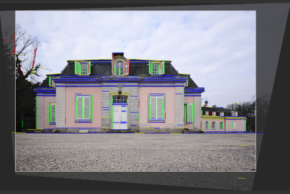
Only lines that form a set of vertical or horizontal converging lines are used for subsequent processing steps. Line segments are displayed as overlays on the image canvas, with the type of line identified by color as follows:
- green
- Vertical converging lines
- red
- Vertical lines that do not converge
- blue
- Horizontal converging lines
- yellow
- Horizontal lines that do not converge
- gray
- Other lines that are not of interest to this module
Lines marked in red or yellow are regarded as outliers and are not taken into account during the automatic fitting step. This outlier elimination involves a statistical process using random sampling which means that each time you press the “get structure” button the color pattern of the lines will look slightly different.
You can manually change the status of line segments: Left-Click on a line to select it (turn the color to green or blue) and Right-click to deselect it (turn the color to red or yellow). If you keep the mouse button pressed, you can use a sweeping action to select/deselect multiple lines in a row. The size of the select/deselect brush can be changed with the mouse wheel. Hold down the Shift key and keep the left or right mouse button pressed while dragging to select or deselect all lines in the chosen rectangular area.
Once you are happy with the detected lines, select a “fit” icon to complete the process.
🔗fit
Once you are happy with the identified horizontal and vertical lines, using one of the methods above, click on one of the “fit” icons to automatically set the module’s parameters based on the defined structure. The image and the overlaid lines are then displayed with perspective corrections applied.
You may choose to automatically apply just the vertical corrections
![]() , just the horizontal corrections
, just the horizontal corrections
![]() , or both together
, or both together
![]() . Ctrl+click on any of the icons to apply a rotation without the lens shift. Shift+click on any of the icons to apply the lens shift without any rotation.
. Ctrl+click on any of the icons to apply a rotation without the lens shift. Shift+click on any of the icons to apply the lens shift without any rotation.
🔗rotate
Once you are happy with the applied perspective corrections, you may wish to perform a final rotation correction either by adjusting the rotation parameter or right-clicking and dragging the image to define a horizontal/vertical line.
🔗module controls
- rotation
- Control the rotation of the image around its center to correct for a skewed horizon. To rotate by more than the default soft limit of ten degrees, right click and enter the desired value up to 180 degrees (see module controls).
- automatic cropping
- When activated, this feature crops the image to remove any black areas at the edges caused by the distortion correction. You can either crop to the “largest area”, or to the largest rectangle that maintains the original aspect ratio (“original format”). In the latter case you can manually adjust the automatic cropping result by clicking in the clip region and moving it around. The size of the region is modified automatically to exclude any black areas.
- lens shift (vertical)
- Correct converging vertical lines (i.e. to make the green lines parallel). In some cases you can obtain a more natural looking image if you correct vertical distortions to an 80 ~ 90% level rather than to the maximum extent. To do this, reduce the correction slider after having performed the automatic correction.
- lens shift (horizontal)
- Correct converging horizontal lines (i.e. to make the blue lines parallel).
- shear
- Shear the image along one of its diagonals. This is required when correcting vertical and horizontal perspective distortions simultaneously.
- lens model
- This parameter controls the lens focal length, camera crop factor and aspect ratio that used by the correction algorithm. If set to “generic” a lens focal length of 28mm on a 35mm full-frame camera is assumed. If set to “specific”, the focal length and crop factor can be set manually using the sliders provided.
- focal length
- If the lens model is set to “specific”, set the lens focal length. The default value is taken from the image’s Exif data, and can be overridden by adjusting the slider manually.
- crop factor
- If the lens model is set to “specific”, set the camera crop factor. You will normally need to set this value manually.
- aspect adjust
- If the lens model is set to “specific”, this parameter allows for a free manual adjustment of the image’s aspect ratio. This is useful for “unsqueezing” images taken with an anamorphic lens (which changes the ratio of image height to width).
- structure
- Define horizontal and vertical lines in the image using a manual or automatic method (see workflow section for details).
- fit
- Set the distortion correction sliders automatically based on the identified structure (see workflow section for details).
- show guides
- Tick the box to show guide overlays whenever the module is activated. Click the icon on the right to control the properties of the guides. See guides & overlays for details.
🔗examples
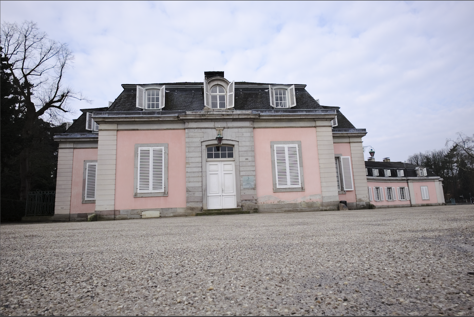
Here is an image with a skewed horizon and converging lines caused by directing the camera upwards:
Here is the image after having corrected for vertical and horizontal perspective distortions using automatic structure detection. Note the framing adjustment made by the automatic cropping feature and the still-visible overlay of structural lines: